
Low inductance module structure 1200V 400A IGBT Power Module
- Product Description
-
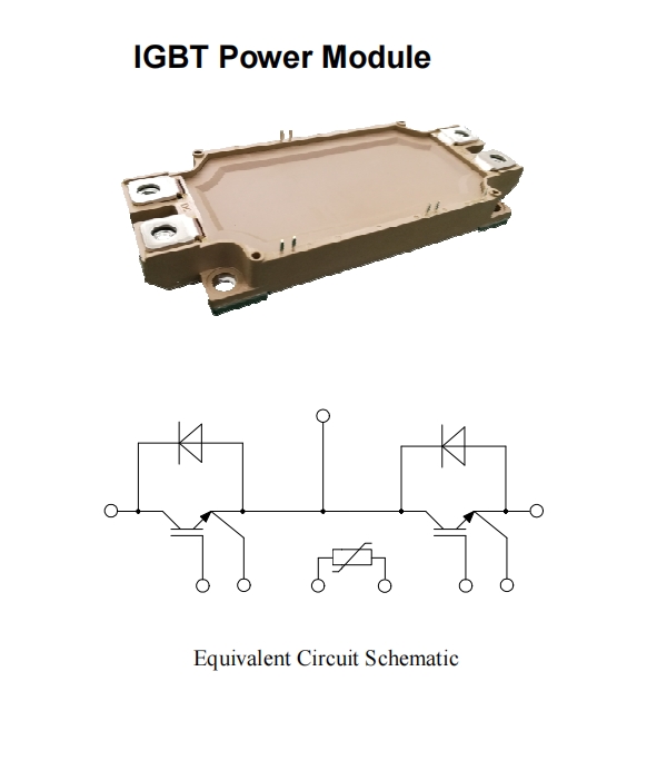
YZPST-FF600R12ME4IGBT Power ModuleApplicationsInverter for motor driveAC and DC servo drive amplifierUPS (Uninterruptible Power Supplies)FeaturesLow Vce(sat) with SPT+ technologyVce(sat) with positive temperature coefficientIncluding fast & soft recovery anti-parallel FWDHigh short circuit capability(10us)Low inductance module structure
Absolute Maximum Ratings
Parameter
Symbol
Conditions
Value
Unit
Collector-Emitter Voltage
VCES
VGE=0V, IC =1mA, Tvj=25℃
1200
V
Continuous Collector Current
IC
Tc=100℃
600
A
Peak Collector Current
ICRM
ICRM=2IC
1200
A
Gate-Emitter Voltage
VGES
Tvj=25℃
±20
V
Total Power Dissipation
(IGBT-inverter)
Ptot
Tc=25℃
Tvjmax=175℃
3750
W
IGBT Characteristics
Parameter Value Unit Symbol Conditions Min. Typ. Max. Gate-emitter Threshold Voltage VGE(th) VGE=VCE, IC =3mA,Tvj=25℃ 5 5.8 6.5 V VCE=1200V,VGE=0V, Tvj=25℃ 1 mA Collector-Emitter Cut-off Current ICES VCE=1200V,VGE=0V, Tvj=125℃ 5 mA Collector-Emitter Ic=600A,VGE=15V, Tvj=25℃ 1.7 V Saturation Voltage VCE(sat) Ic=600A,VGE=15V, Tvj=125℃ 2 V Input Capacitance Cies 43.1 nF Output Capacitance Coes VCE=25V,VGE =0V, 2.25 nF Reverse Transfer Capacitance Cres f=1MHz, Tvj=25℃ 1.95 nF Internal Gate Resistance Rgint 1.25 Ω Turn-on Delay Time td(on) 250 ns Rise Time tr IC =600 A 88 ns Turn-off Delay Time td(off) VCE = 600 V 560 ns Fall Time tf VGE = ±15V 131 ns Energy Dissipation During Turn-on Time Eon RG = 1.2Ω 33.1 mJ Energy Dissipation During Turn-off Time Eoff Tvj=25℃ 57.8 mJ Turn-on Delay Time td(on) 300 ns Rise Time tr IC =600 A 102 ns Turn-off Delay Time td(off) VCE = 600 V 650 ns Fall Time tf VGE = ±15V 180 ns Energy Dissipation During Turn-on Time Eon RG = 1.2Ω 50.2 mJ Energy Dissipation During Turn-off Time Eoff Tvj=125℃ 87.8 mJ Tp≤10us,VGE=15V, SC Data Isc Tvj=150℃,Vcc=600V, 2400 A VCEM≤1200V Package Dimensions


Product Inquiry
We will contact you within one working day. Please pay attention to your email.
* Note: Please be sure to fill in the information accurately and keep the communication unblocked. We will get in touch with you as soon as possible.

Do you want to know more product details? Send us a consultation!
We will contact you within one working day. Please pay attention to your email.
CONTACT
Tel:+86-514-87360558、87782298、87782296
Fax:+86-514-87782297、87367519
E-mail: info@stt.tm / yzpst@pst888.com
WhatsApp: +8613805278321
SKYPE:Microsoft Teams ID:326880628@qq.com
Link: www.yzpst.com / www.pst888.com / www.yzpst.net


