
Low VCE sat Trench IGBT technology 450A IGBT Module 1700V
- Product Description
-
IGBT Module
YZPST-450HFX170C6S1700V/450A 2 in one-packageGeneral Description
IGBT Power Module provides ultra
low conduction loss as well as short circuit ruggedness.
They are designed for the applications such as
general inverters and UPS.
Features
Low VCE(sat) Trench IGBT technology
10μs short circuit capability
VCE(sat) with positive temperature coefficient
Maximum junction temperature 175oC
Low inductance case
Fast & soft reverse recovery anti-parallel FWD
Isolated copper baseplate using DBC technology
Typical ApplicationsInverter for motor drive
AC and DC servo drive amplifier
Uninterruptible power supply
IGBT
Symbol
Description
Value
Unit
VCES
Collector-Emitter Voltage
1700
V
VGES
Gate-Emitter Voltage
±20
V
IC
Collector Current @ TC=25oC
@ TC= 100oC
706
450
A
ICM
Pulsed Collector Current tp=1ms
900
A
PD
 Maximum Power Dissipation @ T =175oC
2542
W
Diode
Symbol
Description
Value
Unit
VRRM
Repetitive Peak Reverse Voltage
1700
V
IF
Diode Continuous Forward Current
450
A
IFM
Diode Maximum Forward Current tp=1ms
900
A
Module
Symbol
Description
Value
Unit
Tjmax
Maximum Junction Temperature
175
oC
Tjop
Operating Junction Temperature
-40 to +150
oC
TSTG
Storage Temperature Range
-40 to +125
oC
VISO
Isolation Voltage RMS,f=50Hz,t=1min
4000
V
IGBT Characteristics TC=25oC unless otherwise noted
Symbol Parameter Test Conditions Min. Typ. Max. Unit IC=450A,VGE=15V, Tj=25oC 1.85 2.2 VCE(sat) Collector to Emitter IC=450A,VGE=15V, Tj=125oC 2.25 V Saturation Voltage IC=450A,VGE=15V, Tj=150oC 2.35 VGE(th) Gate-Emitter Threshold Voltage IC= 18.0mA,VCE=VGE, Tj=25oC 5.6 6.2 6.8 V ICES Collector Cut-Off VCE=VCES,VGE=0V, 5 mA Current Tj=25oC IGES Gate-Emitter Leakage Current VGE=VGES,VCE=0V, Tj=25oC 400 nA RGint Internal Gate Resistance 1.67 Ω Cies Input Capacitance VCE=25V,f=1MHz, 54.2 nF Cres Reverse Transfer VGE=0V 1.32 nF Capacitance QG Gate Charge VGE=- 15…+15V 4.24 μC td(on) Turn-On Delay Time 179 ns tr Rise Time 105 ns td(off) Turn-Off Delay Time VCC=900V,IC=450A, RG=3.3Ω,VGE=±15V, Tj=25oC 680 ns tf Fall Time 375 ns Eon Turn-On Switching 116 mJ Loss Eoff Turn-Off Switching 113 mJ Loss td(on) Turn-On Delay Time 208 ns tr Rise Time 120 ns td(off) Turn-Off Delay Time VCC=900V,IC=450A, RG=3.3Ω,VGE=±15V, Tj= 125oC 784 ns tf Fall Time 613 ns Eon Turn-On Switching 152 mJ Loss Eoff Turn-Off Switching 171 mJ Loss td(on) Turn-On Delay Time 208 ns tr Rise Time 120 ns td(off) Turn-Off Delay Time VCC=900V,IC=450A, RG=3.3Ω,VGE=±15V, Tj= 150oC 800 ns tf Fall Time 720 ns Eon Turn-On Switching 167 mJ Loss Eoff Turn-Off Switching 179 mJ Loss tP≤10μs,VGE=15V, ISC SC Data Tj=150oC,VCC= 1000V, VCEM≤1700V 1800 A Diode Characteristics TC=25oC unless otherwise noted
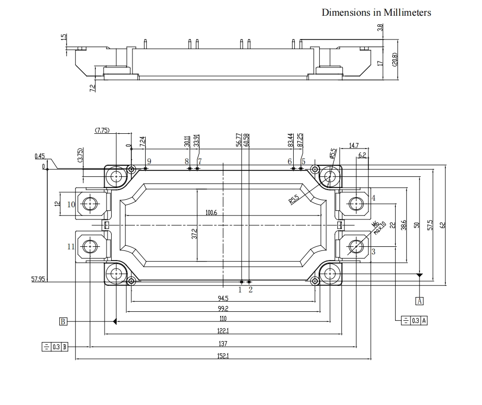
Symbol Parameter Test Conditions Min. Typ. Max. Unit Diode Forward IF=450A,VGE=0V,Tj=25oC 1.8 2.25 VF Voltage IF=450A,VGE=0V,Tj= 125oC 1.95 V IF=450A,VGE=0V,Tj= 150oC 1.9 Qr Recovered Charge VR=900V,IF=450A, 105 μC IRM Peak Reverse -di/dt=4580A/μs,VGE=- 15V Tj=25oC 198 A Recovery Current Erec Reverse Recovery Energy 69 mJ Qr Recovered Charge VR=900V,IF=450A, 187 μC IRM Peak Reverse -di/dt=4580A/μs,VGE=- 15V Tj= 125oC 578 A Recovery Current Erec Reverse Recovery Energy 129 mJ Qr Recovered Charge VR=900V,IF=450A, 209 μC IRM Peak Reverse -di/dt=4580A/μs,VGE=- 15V Tj= 150oC 585 A Recovery Current Erec Reverse Recovery Energy 150 mJ Package Dimensions


Product Inquiry
We will contact you within one working day. Please pay attention to your email.
* Note: Please be sure to fill in the information accurately and keep the communication unblocked. We will get in touch with you as soon as possible.

Do you want to know more product details? Send us a consultation!
We will contact you within one working day. Please pay attention to your email.
CONTACT
Tel:+86-514-87360558、87782298、87782296
Fax:+86-514-87782297、87367519
E-mail: info@stt.tm / yzpst@pst888.com
WhatsApp: +8613805278321
SKYPE:Microsoft Teams ID:326880628@qq.com
Link: www.yzpst.com / www.pst888.com / www.yzpst.net


